In shortBlockChannelCoding. m, there are only modulation methods such as QAM/bpsk/QPSK. If I want to use OFDM modulation, how should I modify the code?
Hi,
In the Examples folders, you can find the file Comparison_Waveforms.m, where different waveforms, including OFDM, are compared. There, you can find how you can construct the modulator object, channel object, etc.
The code there uses uncoded bit stream, and therefore you would need to add the channel encoding step, as well as the channel decoding, as in the coding example. In the bit detection step, instead of using Symbol2Bit(), which produces hard decisions, you should use LLR_AWGN(), with the passed noise power being scaled by the channel, to produce soft decisions (LLRs), again similar to the coding example.
Best regards,
Bashar
% =====================================================================
% Ronald Nissel, rnissel@nt.tuwien.ac.at
% (c) 2017 by Institute of Telecommunications, TU Wien
% www.nt.tuwien.ac.at
% =====================================================================
%此脚本模拟时变多路径上的误码率
%不同多载波调制的信道(双选择信道)
%技术:
%1)具有CP的OFDM(最差频谱行为)
%2)FBMC(最佳频谱特性,复正交性被实正交性取代)
%3)WOLA(加窗OFDM。加窗在TX和RX处完成)
%4)FOFDM(滤波OFDM,sinc+Hann,TX和RX滤波)
%5)UFMC(支持滤波OFDM、子带滤波、Dolph-Chebyshev窗口、循环前缀和零填充,在TX和RX进行滤波)
% close all;
clear;
cd(‘…’);
addpath(‘./Examples/Theory’);
% FBMC参数
FBMC_NumberOfSubcarriers = 24; % 子载波数
FBMC_NumberOfSymbolsInTime = 30; % FBMC符号的时间编号
FBMC_SubcarrierSpacing = 15e3; % 副载波间隔(Hz)
FBMC_PrototypeFilter = ‘Hermite-OQAM’; % 原型滤波器(Hermite、PHYDYAS、RRC)和OQAM或QAM。与OQAM相比,QAM的数据速率降低了两倍,但在双选择性信道中具有鲁棒性。注意,我们的模拟对QAM不再有效,因为我们传输实值符号,但可以使用QAM传输复值符号
FBMC_OverlappingFactor = 4; % 重叠系数,2,3,4,。。。
% 仿真参数
Simulation_SNR_OFDM_dB = [-5:5:35]; % OFDM的信噪比(dB)。所有方法的平均发射功率是相同的!然而,由于滤波(在FOFDM和UFMC中)或由于使用不同的带宽(不同的子载波间隔或不同数量的子载波),SNR可能不同。
Simulation_MonteCarloRepetitions = 1000; % 我们取平均值的蒙特卡罗重复次数
Simulation_PlotSignalPowerTheory = true; % 如果为TRUE,则绘制理论预期发射功率随时间的变化图
% 信道参数
Channel_Velocity_kmh = 130; % 速度(km/h)。注意[mh]*1.6=[kmh]和[m/s]*3.6=[km h]
Channel_PowerDelayProfile = ‘VehicularA’; % 矢量: ‘Flat’, ‘AWGN’, ‘PedestrianA’, ‘PedestrianB’, ‘VehicularA’, ‘VehicularB’, ‘ExtendedPedestrianA’, ‘ExtendedPedestrianB’, or ‘TDL-A_xxns’,‘TDL-B_xxns’,‘TDL-C_xxns’ (其中xx是以ns为单位的RMS延迟扩展,例如。‘TDL-A_30ns’), or [1 0 0.2] (取决于采样率的自定义功率延迟分布)
Channel_DopplerModel = ‘Jakes’; % 哪个多普勒模型: ‘Jakes’, ‘Uniform’, ‘Discrete-Jakes’, ‘Discrete-Uniform’. For “Discrete-”, 我们假设一个离散的多普勒频谱,以提高仿真时间。 仅当采样数和速度足够大时,此方法才能准确工作
Channel_CarrierFrequency = 2.5e9; % 载波频率(Hz)
% 通用调制参数
QAM_ModulationOrder = 64; % QAM信号星座顺序:4,16,64256,,。。。
% OFDM 参数
OFDM_NumberOfSubcarriers = 24; % 子载波数
OFDM_NumberOfSymbolsInTime = 14; % 时间上的OFDM符号数量
OFDM_SubcarrierSpacing = 15e3; % 副载波间隔(Hz)副载波间隔(Hz)副载波间隔(Hz)
OFDM_CyclicPrefixLength = 1/(14*OFDM_SubcarrierSpacing); % 循环前缀的长度
% 采样率:应大致匹配信道的功率延迟配置文件,并且必须大于“子载波间距子载波数量”。
SamplingRate = 15e314*14;
dt = 1/SamplingRate;
%% Generate " +Modulation" Objects(生成“+调制\”对象)
% FBMC对象
FBMC = Modulation.FBMC(…
FBMC_NumberOfSubcarriers,… % 子载波数
FBMC_NumberOfSymbolsInTime,… % FBMC符号的时间编号
FBMC_SubcarrierSpacing,… % 副载波间隔(Hz)
SamplingRate,… % 采样率(样本/s)
0,… % 第一个子载波的中频(Hz)。必须是子载波间隔的倍数
false,… % 传输实值信号(必须满足采样定理!)
FBMC_PrototypeFilter,… % 原型滤波器(Hermite、PHYDYAS、RRC)和OQAM或QAM。与OQAM相比,QAM的数据速率降低了两倍,但在双选择信道中增强了鲁棒性
FBMC_OverlappingFactor, … % 重叠因子(也决定频域中的过采样)
0, … % 初始相移
true … % 多阶段实施
);
FBMC_BlockOverlapTime = (FBMC.PrototypeFilter.OverlappingFactor-1/2)*FBMC.PHY.TimeSpacing;
% OFDM对象
OFDM = Modulation.OFDM(…
OFDM_NumberOfSubcarriers,… % 子载波数
OFDM_NumberOfSymbolsInTime,… % 时间上的OFDM符号数量
OFDM_SubcarrierSpacing,… % 副载波间隔(Hz)
SamplingRate,… % 采样率(样本/s)
0,… % 第一个子载波的中频(Hz)。必须是子载波间隔的倍数
false,… % 传输实值信号(必须满足采样定理!)
OFDM_CyclicPrefixLength, … %循环前缀的长度
FBMC_BlockOverlapTime … % 保护时间的长度,即传输开始和结束时为零
);
% 样品数量
N_OFDM = OFDM.Nr.SamplesTotal;
N = max(N_OFDM );
dummy.spatialChannelModel = false; % 为空间通道模型结构创建虚拟对象
ChannelModel = Channel.FastFading(…
SamplingRate,… % 采样率(样本/s)
Channel_PowerDelayProfile,… % 功率延迟配置文件,字符串或矢量: ‘Flat’, ‘AWGN’, ‘PedestrianA’, ‘PedestrianB’, ‘VehicularA’, ‘VehicularB’, ‘ExtendedPedestrianA’, ‘ExtendedPedestrianB’, or ‘TDL-A_xxns’,‘TDL-B_xxns’,‘TDL-C_xxns’ (with xx the RMS delay spread in ns, e.g. ‘TDL-A_30ns’), or [1 0 0.2] (Self-defined power delay profile which depends on the sampling rate)
N,… % 样本总数
Channel_Velocity_kmh/3.6Channel_CarrierFrequency/2.998e8,… % 最大多普勒频移: Velocity_kmh/3.6CarrierFrequency/2.998e8
Channel_DopplerModel,… % 哪个多普勒模型: ‘Jakes’, ‘Uniform’, ‘Discrete-Jakes’, ‘Discrete-Uniform’. For “Discrete-”, we assume a discrete Doppler spectrum to improve the simulation time. This only works accuratly if the number of samples and the velocity is sufficiently large
200, … % WSSUS进程的路径数。仅与“Jakes”和“Uniform”多普勒频谱相关
false,… % 通道时间相关性
‘none’,… % MIMO信道的空间相关性
0,… % 发射侧空间相关系数
0,… % 接收侧空间相关系数
1,… % 发射天线数量
1,… %接收天线数量
true,… % 如果通道的预定义延迟抽头不符合采样率,则发出警告。如果它们大致相同,这通常不是什么大问题。
0,… % TWDP K参数
1,… % TWDP增量参数
dummy,… % 空间通道模型;本例不需要
[1,1],… % Tx水平和垂直天线的数量
[1,1],… % Rx水平和垂直天线的数量
Channel_CarrierFrequency,… % 载波频率
1 …
);
% PAM和QAM对象
PAM = Modulation.SignalConstellation(sqrt(QAM_ModulationOrder),‘PAM’,0,‘Max-Log’);
QAM = Modulation.SignalConstellation(QAM_ModulationOrder,‘QAM’,0,‘Max-Log’);
K = 1006;
R=1/2;
%% 信道编码器
coderLDPC = Coding.ChannelCoding(‘LDPC’, ‘PWL-Min-Sum’, R,32); %32指的迭代次数
coderPolar = Coding.ChannelCoding(‘Polar’, ‘CRC-List-SC’, R, 8);
coderTurbo = Coding.ChannelCoding(‘Turbo’, ‘Linear-Log-MAP’, R, 16); %16指的迭代次数
coderConv = Coding.ChannelCoding(‘TB-Convolutional’, ‘Max-Log-MAP’, R);
%% 初始化
% Force CRC-16(循环冗余校验算法,生成多项式为16位长度)
coderLDPC.CustomCRC = 1;%指示是否选择了非标准CRC
coderPolar.CustomCRC = 1;
coderTurbo.CustomCRC = 1;
coderConv.CustomCRC = 1;
coderLDPC.CRCPoly = ‘16’;
coderLDPC.CRCLength = 16;
coderPolar.CRCPoly = ‘16’;
coderPolar.CRCLength = 16;
coderTurbo.CRCPoly = ‘16’;
coderTurbo.CRCLength = 16;
coderConv.CRCPoly = ‘16’;
coderConv.CRCLength = 16;
% 更新对象
coderLDPC.update (‘Input’, K, 1, R, log2(QAM_ModulationOrder), 1);
%k是信息长度48,1是码字被映射到的空间层的数量,R是码率,log2(m odOrder)意味着每个调制符号携带了 2 个比特的信息,1为控制速率匹配软缓冲区的长度
coderPolar.update(‘Input’, K, 1, R, log2(QAM_ModulationOrder), 1);
coderTurbo.update(‘Input’, K, 1, R, log2(QAM_ModulationOrder), 1);
coderConv.update (‘Input’, K, 1, R, log2(QAM_ModulationOrder), 1);
%% 开始模拟
tic
error_counts= zeros(length(Simulation_SNR_OFDM_dB), 4); % 4代表四种编码方案
for i_rep = 1:Simulation_MonteCarloRepetitions
for i_SNR = 1:length(Simulation_SNR_OFDM_dB)
% 更新信道
ChannelModel.NewRealization;
% 编码方案循环的索引
coderNames = {‘Conv’, ‘Turbo’, ‘LDPC’, ‘Polar’};
for coderIndex = 1:length(coderNames)
% 根据coderIndex选择编码方案
switch coderIndex
case 1
coderIn = coderConv;
case 2
coderIn = coderTurbo;
case 3
coderIn = coderLDPC;
case 4
coderIn = coderPolar;
end
% 二进制数据
BinaryDataStream_OFDM = randi([0 1],K,1);
%编码
CodedBits = coderIn.encode(BinaryDataStream_OFDM );
% 传输的数据符号(将二进制数据映射到符号)
x_OFDM = reshape(QAM.Bit2Symbol(CodedBits),OFDM.Nr.Subcarriers,OFDM.Nr.MCSymbols);
% 时域中的传输信号(这行代码执行OFDM调制过程。它将调制后的数据x_OFDM转换为时域信号s_OFDM,这个时域信号包含了要通过无线信道发送的OFDM符号。)
s_OFDM = OFDM.Modulation(x_OFDM);
% 通道卷积(模拟了多径效应等信道特性。r_OFDM_noNoise是通过信道传输后的接收信号,此时还没有考虑噪声的影响。)
r_OFDM_noNoise  = ChannelModel.Convolution(s_OFDM);

% 单抽头均衡器的信道(仅代表近似值,因为没有考虑脉冲前)(ChannelModel.GetTransferFunction方法获取信道在特定频率点的响应,用于后续的信号均衡处理。这些频率点对应于OFDM系统中使用的子载波频率。)
h_OFDM  = ChannelModel.GetTransferFunction(OFDM.GetTimeIndexMidPos,OFDM.Implementation.FFTSize,(1:OFDM.Nr.Subcarriers)+OFDM.Implementation.IntermediateFrequency);

% 添加噪声
SNR_OFDM_dB = Simulation_SNR_OFDM_dB(i_SNR);%该数组预先定义了要模拟的不同SNR水平。

Pn_time     = 1/mean(mean(OFDM.GetSymbolNoisePower(1)))*10^(-SNR_OFDM_dB/10);
%算时域中的噪声功率Pn_time。这里使用OFDM.GetSymbolNoisePower(1)获取一个OFDM符号的平均噪声功率,然后通过SNR计算出对应的噪声功率水平。
noise       = sqrt(Pn_time/2)*(randn(length(s_OFDM),1)+1j*randn(length(s_OFDM),1));
%生成复高斯噪声,其实部和虚部均为高斯分布,噪声的功率由之前计算的Pn_time确定。因为复信号的功率是实部和虚部功率的和,所以每部分乘以sqrt(Pn_time/2)。

r_OFDM  = r_OFDM_noNoise  + noise(1:N_OFDM);%将噪声加到无噪声信号r_OFDM_noNoise上,得到接收信号r_OFDM。

% 解调OFDM信号
y_OFDM  = OFDM.Demodulation(r_OFDM);%将接收到的信号r_OFDM进行OFDM解调,恢复出调制前的数据符号y_OFDM

% 单抽头均衡器
y_OneTapEqualizer_OFDM  = y_OFDM./h_OFDM;%使用单抽头均衡器处理解调后的信号y_OFDM,以补偿信道造成的失真。均衡器使用之前计算的信道传输函数h_OFDM。

% 使用接收符号和噪声功率计算LLR值
LLR_OFDM = -QAM.LLR_AWGN(y_OneTapEqualizer_OFDM(:), Pn_time);

DecodedBits = coderIn.decode(LLR_OFDM );%对检测到的比特流进行解码,恢复出原始的二进制数据流DecodedBits

% 累加当前SNR下的错误数
error_counts(i_SNR, coderIndex) =  error_counts(i_SNR, coderIndex)+sum(BinaryDataStream_OFDM ~= DecodedBits);

end

 end
     fprintf('Repetition %i/%i completed.\n', i_rep, Simulation_MonteCarloRepetitions);
end
% 计算平均BER
mean_BER_OFDM = error_counts/(K*Simulation_MonteCarloRepetitions);
%% 绘图部分
hold on; % 开始绘图并保持图形,以便在同一图上添加多条线
markerStyles = {‘o’, ‘^’, ‘s’, ‘x’}; % 定义标记样式:圆圈,上三角,正方形,叉号
coderNames = {‘卷积码’, ‘Turbo码’, ‘LDPC码’, ‘Polar码’};
for i = 1:length(coderNames)
semilogy(Simulation_SNR_OFDM_dB, mean_BER_OFDM(:, i), ‘Marker’, markerStyles{i}, ‘DisplayName’, coderNames{i});
end
% 设置图表属性
set(gca, ‘YScale’, ‘log’);
xlabel(‘信噪比 (dB)’);
ylabel(‘误码率 (BER)’);
grid on; % 开启主要网格线
ylim([1e-4, 1e-0]);
legend(‘-DynamicLegend’, ‘location’, ‘best’);
hold off; % 结束绘图
Thank you for your guidance. I have now implemented four channel codes in OFDM modulation schemes. Now, I have another question. If I want to use OTFS, I will switch from OFDM to OTFS. I only need to go through ISFFT first and then SFFT, but I find it difficult to implement the specific code. Do you have any suggestions?
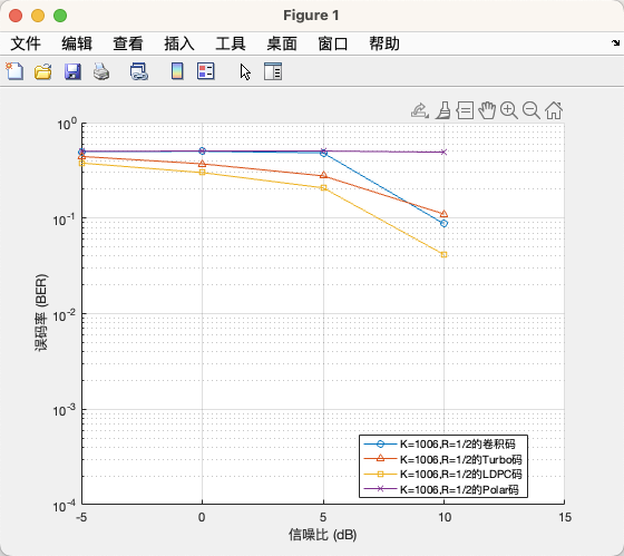
Under 64qam modulation, the polar code has K=1006 and R=1/2; Why is the error rate of polar codes so high, even higher than that of convolutional codes? Is this a normal situation?
Hello,
The polar code implemented in the simulator is based on a non-systematic construction. Non-systematic codes, in general, have worse performance at low SNR, compared to their systematic counterparts. This is because for systematic codes, if the decoding fails, then one can still recover parts of the input bits from the systematic part of the codeword. For non-systematic codes, the input bits do not show up in the codeword, and therefore if the decoding fails, then generally non of the original bits can be retrieved.
After you reach sufficiently high SNR, then the decoding gain will kick in and you will start to see low BER. In your setup above, you are using a large SNR stepsize. Decrease your stepsize, i.e., instead of 5 dB, use an SNR step of 1 dB (or even less) within the SNR range of 10-15 dB.
Best regards,
Bashar