% Massive MIMO Simulation Scenario
%
% The scenario consists of two base stations (BSs). Each BS performs a
% downlink transmission to four connected users using massive MIMO. The first
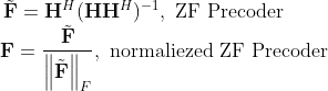
% BS employs ZF precoding, while the second BS employs MRT. As the number of
% BS antennas increases, the sum throughput of MRT approaches that of ZF.
%% Topology
scStr.topology.nodes = [‘BS1,BS2,UE1,UE2,UE3,UE4,UE5,UE6,UE7,UE8’];
scStr.topology.primaryLinks = [‘BS1:UE1,’ …
‘BS1:UE2,’ …
‘BS1:UE3,’ …
‘BS1:UE4,’ …
‘BS2:UE5,’ …
‘BS2:UE6,’ …
‘BS2:UE7,’ …
‘BS2:UE8,’ …
‘UE1:BS1,’ …
‘UE2:BS1,’ …
‘UE3:BS1,’ …
‘UE4:BS1,’ …
‘UE5:BS2,’ …
‘UE6:BS2,’ …
‘UE7:BS2,’ …
‘UE8:BS2’ …
];
scStr.topology.jointTxRxLinks = [’’];
scStr.topology.interferenceGeneration = ‘Automatic’;
scStr.topology.attenuation = 300;
scStr.topology.interferingLinks = [ ];
%% General Simulation Parameters
% Set link types to simulate
scStr.simulation.simulateDownlink = true;
scStr.simulation.simulateUplink = true;
scStr.simulation.simulateD2D = false;
% set duplexing mode (frame structure)
scStr.simulation.frameStructure = ‘FDD’; % may be ‘TDD’ or ‘FDD’
scStr.simulation.plotResultsFor = [1];
scStr.simulation.plotOverSNR = false;
scStr.simulation.plotPAPR = false;
scStr.simulation.saveData = false;
scStr.simulation.sweepParam = {‘simulation.nAntennasBaseStation’};
scStr.simulation.sweepValue = [4, 8, 12, 16, 24, 32, 64];
scStr.simulation.applySweepingTo = [1];
scStr.simulation.nFrames = 100;
%% Physical Transmission Parameters
scStr.simulation.centerFrequency = 2.5e9;
scStr.simulation.txPowerBaseStation = [0];
scStr.simulation.txPowerUser = [0];
% Antennas settings
scStr.simulation.codebook = ‘LTE’;
scStr.simulation.nAntennasBaseStation = [16];
scStr.simulation.antennaConfiguration = {[4,4]};
scStr.simulation.nAntennasUser = [1];
scStr.simulation.userVelocity = [5/3.6];
scStr.simulation.pathloss = [100];
% Nonlinearity model
scStr.simulation.nonlinearity = false;
scStr.simulation.amplifierOBO = [1];
scStr.simulation.smoothnessFactor = [3];
%% Channel Parameters
scStr.channel.dopplerModel = ‘Jakes’;
scStr.channel.timeSubsamplingFactor = 10;
scStr.channel.correlatedFrames = true;
scStr.channel.spatialCorrelation = ‘none’;
scStr.channel.nPaths = 50;
scStr.channel.powerDelayProfile = ‘PedestrianA’;
scStr.channel.K = 0;
scStr.channel.delta = 1;
scStr.channel.spatialChannelModel = false;
scStr.channel.nSpatialPaths = [10];
scStr.channel.angleMeanAOA = [90,60,45];
scStr.channel.angleMeanZOA = [45];
scStr.channel.angleSigmaAOA = [5];
scStr.channel.angleSigmaZOA = [5];
scStr.channel.kFactor = [5];
scStr.channel.antennaSpacing = [1/2];
%% Channel Estimation and Equalization Parameters
scStr.simulation.channelEstimationMethod = ‘Approximate-Perfect’;
scStr.simulation.noisePowerEstimation = false;
scStr.simulation.pilotPatternDownlink = ‘LTE Uplink’;
scStr.simulation.pilotPatternUplink = ‘LTE Uplink’;
scStr.simulation.pilotSpacingFrequency = 12;
scStr.simulation.pilotSpacingTime = 6;
scStr.simulation.pilotSequenceLength = 6;
scStr.simulation.receiverTypeMIMO = ‘MMSE’;
%% MIMO Parameters
% Layer mapping
scStr.layerMapping.mode = ‘LTE’;
scStr.layerMapping.table.Uplink = {1;2;[1,2]};
scStr.layerMapping.table.Downlink = {1;2;[1,2]};
% MIMO mode
scStr.modulation.transmissionMode = ‘custom’;
scStr.schedule.multiuserMode.Downlink = {‘ZF-MUMIMO’, ‘MRT-MUMIMO’};
scStr.schedule.multiuserMode.Uplink = {‘ZF-MUMIMO’, ‘MRC-MUMIMO’};
scStr.modulation.delayDiversity = 1;
%% Feedback Parameters
scStr.feedback.delay = 0;
scStr.feedback.averager.Type = ‘miesm’;
scStr.feedback.enable = true;
scStr.feedback.pmi = false;
scStr.feedback.ri = false;
scStr.feedback.cqi = true;
scStr.modulation.cqiTable = 0;
scStr.modulation.nStreams = [1];
scStr.modulation.precodingMatrix{1} = nan; % No need to set it when multiuserMode is MUMIMO
scStr.modulation.mcs = [8];
scStr.modulation.MUSTIdx = [2];
%% Modulation Parameters
% Waveform
scStr.modulation.waveform = {‘OFDM’};
scStr.modulation.spreadingTransformDownlink = ‘none’;
scStr.modulation.spreadingTransformUplink = ‘none’;
% Parameters for FBMC
scStr.modulation.prototypeFilter = ‘PHYDYAS-OQAM’;
% Parameters for UFMC
scStr.modulation.nSubcarriersPerSubband = [12];
% Numerology setup
scStr.modulation.numberOfSubcarriers = [72];
scStr.modulation.subcarrierSpacing = [15e3];
scStr.modulation.nSymbolsTotal = [15];
scStr.modulation.nGuardSymbols = [1];
scStr.modulation.samplingRate = ‘Automatic’;
%% Channel Coding Parameters
scStr.coding.code = {‘Turbo’};
scStr.coding.decoding = {‘Max-Log-MAP’};
scStr.coding.decodingIterations = [8];
scStr.coding.LLRsCalculationMethod = ‘Max-Log’;
scStr.coding.softBufferRatio = [1];
%% Schedule
scStr.schedule.fixedScheduleDL{1} = [‘UE1:72,UE2:UE1,UE3:UE1,UE4:UE1’];
scStr.schedule.fixedScheduleDL{2} = [‘UE5:72,UE6:UE5,UE7:UE5,UE8:UE5’];
scStr.schedule.fixedScheduleUL{1} = [‘UE1:72,UE2:UE1,UE3:UE1,UE4:UE1’];
scStr.schedule.fixedScheduleUL{2} = [‘UE5:72,UE6:UE5,UE7:UE5,UE8:UE5’];