NOMA scenario adaptation for different CQI table and uplink

Dear VCCS team,

I am working on testing different NOMA scenarios in LL v1.2. I have a few questions.

  1. I see that the number of bits that are used in simulation can be found in user results as nCodeBits. Is there a way to set some other values for bits per simulation other than the ones that are calucalted in these results? Are these values related to the layer mapping table?
  2. Which propagation model is used in LL simulator? Is there a way to adjust model to, for example, UMa or UMi propagation models?
  3. When trying to change CQI table from 0 to 1 or 2, I get the following error:

The source code (C:\Users\user\Downloads\5GLLSimulator\5GLLSimulator\main.m) for the parfor-loop that is trying to execute on the worker could not be found.
Caused by:
Unrecognized function or variable ‘c’.
Error using remoteParallelFunction (line 84)
Worker unable to find file.
Unrecognized function or variable ‘c’.

I’ve left all the other parameters in NOMA scenario the same as they were in default scenario. Are there some other parameters that I shold consider changing in order to be able to change CQI tables to 1 or 2?

  1. I am trying to test out the NOMA uplink scenario with similar settings as the default one for downlink, but it seems I have problems with precoding matrix. I’ve set the coding matrix to be 2x1 dimension because of 2 antennas on the BS and 1 used stream, but I still get the error: The precoding matrix defined for link 1 does not fit number of antennas and streams defined for the link.

This is my code:

%% Topology
% Specifiy all the nodes in ascending order with starting
% index of 1 (BS0 or UE0 is not allowed).
scStr.topology.nodes = [‘BS1,BS2,UE1,UE2,UE3,UE4’];

% Primary (desired) links
scStr.topology.primaryLinks = [‘UE1:BS1,’…
‘UE2:BS1,’…
‘UE3:BS2,’…
‘UE4:BS2,’
];

% Links for Joint Tranmission and Detection (future work)
scStr.topology.jointTxRxLinks = [‘’];

% Interference Links
scStr.topology.interferenceGeneration = ‘Automatic’;

scStr.topology.attenuation = 300; % in dB, set a very high attenuation level to virtually decouple the two BS
scStr.topology.interferingLinks = [];

%% General Simulation Parameters
% set link types to simulate
scStr.simulation.simulateDownlink = false; % downlink
scStr.simulation.simulateUplink = true; % uplink
scStr.simulation.simulateD2D = false; % device to device links

scStr.simulation.frameStructure = ‘FDD’; % ‘TDD’ or ‘FDD’

% Plot options
scStr.simulation.plotResultsFor = [1];
scStr.simulation.plotOverSNR = false;
scStr.simulation.plotPAPR = false;

scStr.simulation.saveData = false;

% Define a sweep parameter
scStr.simulation.sweepParam = {‘simulation.txPowerBaseStation’}; % Define the parameter to sweep over. This can be almost any simulation parameter.
% Most likely it will be the pathloss to obtain results over SNR.

scStr.simulation.sweepValue = [-40:5:60]; % Define parameter values to sweep over, in dB. A good starting point for the pathloss is 150 to 110
scStr.simulation.applySweepingTo = [1];

% Number of simulation frames
scStr.simulation.nFrames = 100; % Number of frames to simulate per sweep value, adjust to obtain sufficiently small confidence intervals.

%% Physical Transmission Parameters
scStr.simulation.centerFrequency = 2.5e9; % center frequency

scStr.simulation.txPowerBaseStation = [30]; % per BS; base station total transmit power in dBm
scStr.simulation.txPowerUser = [30]; % per UE; user total transmit power in dBm

scStr.simulation.codebook = ‘LTE’; % LTE or 5G
scStr.simulation.nAntennasBaseStation = [2]; % per BS; number of antennas at the base station
scStr.simulation.antennaConfiguration = {[2,1],[2,1]}; % per BS: if the 5G codebook is selected, each vector represents the number of horizontal and vertical antennas[N1,N2]
% Supported configurations (N1,N2):
% 4 Ports: (2,1)
% 8 Ports: (2,2), (4,1)
% 12 Ports: (3,2),(6,1)
% 16 Ports: (4,2), (8,1)
% 24 Ports: (4,3), (6,2),(12,1)
% 32 Ports: (4,4), (8,2), (16,1)
scStr.simulation.nAntennasUser = [1]; % per UE; number of antennas at the user
scStr.simulation.userVelocity = [0]; % per UE; velocity in m/s

% Links to UE1 and UE3 have pathloss of 80, UE2 and UE4 of 90, and UE5 and UE6 of 110 and 115, respectively (cell edge).
scStr.simulation.pathloss = [80,110,80,110]; % per Link, channel pathloss in dB, this is most likely swept over

% Nonlinearity model
scStr.simulation.nonlinearity = false; % Apply Rapp’s PA nonlinear model: Rapp, C. “Effects of HPA-nonlinearity on a 4-DPSK/OFDM-signal for a digital sound broadcasting signal.”
scStr.simulation.amplifierOBO = [1]; % Amplifier output back-off, per Link, in dB
scStr.simulation.smoothnessFactor = [3]; % Smoothness factor for the Rapp model, per Link, >=0

%% Channel Parameters
scStr.channel.spatialChannelModel = false; % for a 3D channel, this parameter has to be set to ture
scStr.channel.dopplerModel = ‘Discrete-Jakes’;
scStr.channel.timeSubsamplingFactor = 10;
scStr.channel.correlatedFrames = false;
scStr.channel.spatialCorrelation = ‘none’;
scStr.channel.nPaths = 50;
scStr.channel.powerDelayProfile = ‘PedestrianA’;
scStr.channel.K = 0;
scStr.channel.delta = 1;

%% Channel Estimation and Equalization Parameters
scStr.simulation.channelEstimationMethod = ‘Approximate-Perfect’;
scStr.simulation.noisePowerEstimation = false;
scStr.simulation.pilotPatternDownlink = ‘Diamond’; % pilot symbol allocation pattern for Downlink links
scStr.simulation.pilotPatternUplink = ‘LTE Uplink’; % pilot symbol allocation pattern for Uplink links
scStr.simulation.pilotSpacingFrequency = 6; % pilot spacing in frequency domain (may be fractions of subcarriers)
scStr.simulation.pilotSpacingTime = 3.5; % pilot spacing in time domain (may be fraction of symbols)
scStr.simulation.pilotSequenceLength = 12; % length of orthogonal pilot symbol sequence
scStr.simulation.receiverTypeMIMO = ‘MMSE’;

%% MIMO Parameters
% Layer mapping
scStr.layerMapping.mode = ‘5G’;
scStr.layerMapping.table.Uplink = {1;2;[1,2]};
scStr.layerMapping.table.Downlink = {1;2;[1,2]};

% MIMO mode
scStr.modulation.transmissionMode = ‘custom’;
scStr.schedule.multiuserMode.Downlink = {‘custom’}; % per BS. Right now ‘MUST’, ‘ZF-MUMIMO’, ‘BD-MUMIMO’ and ‘MRT-MUMIMO’ are supported
scStr.schedule.multiuserMode.Uplink = {‘none’,‘ZF-MUMIMO’};
scStr.modulation.delayDiversity = 1;

%% Feedback Parameters
scStr.feedback.delay = 0;
scStr.feedback.averager.Type = ‘miesm’;
scStr.modulation.cqiTable = 0;

% for the custom transmission mode the following parameters are used to configure the feedback
scStr.feedback.enable = false; % this parameter is ignored, the feedback is automatically enabled for the CLSM transmission mode
scStr.feedback.pmi = false;
scStr.feedback.ri = false;
scStr.feedback.cqi = true;

scStr.modulation.nStreams = [1]; % per Link; number of active spatial streams
scStr.modulation.mcs = [15]; % parameter is unused
% Per link, precoder selection (used when feedback is disabled)
scStr.modulation.precodingMatrix{1} = 1/sqrt(2)*ones(2,1); % per Link; employed precoding matrix
% MUST power allocation
scStr.modulation.MUSTIdx = [0, 2]; % per BS; the power allocation index of the 3GPP MUST mode = {0, 1, 2, 3}.

%% Modulation Parameters
% waveform
scStr.modulation.waveform = {‘OFDM’};
scStr.modulation.spreadingTransformDownlink = ‘none’;
scStr.modulation.spreadingTransformUplink = ‘none’;
% parameters for FBMC
scStr.modulation.prototypeFilter = ‘PHYDYAS-OQAM’; % unused for OFDM
% Parameters for UFMC
scStr.modulation.nSubcarriersPerSubband = [12]; % number of subcarriers per subband

% time and bandwidth setup (number of subcarriers, frame duration, CP
% length, sampling rate)
scStr.modulation.numberOfSubcarriers = [72]; % per BS; number of used subcarriers
scStr.modulation.subcarrierSpacing = [15e3]; % per BS; per base station in Hz
scStr.modulation.nSymbolsTotal = [15]; % per BS; total number of time-symbols per frame, the frame duration will be nSymbolsTotal/subcarrierSpacing
scStr.modulation.nGuardSymbols = [1]; % per BS; select how many of the total time-symbols will be used as guard symbols (cyclic prefix in OFDM)
scStr.modulation.samplingRate = ‘Automatic’; % sampling rate has to be the same for all nodes (across all base stations):
% either numeric value for manual setting or ‘Automatic’

%% Channel Coding Parameters
% All links are operating with the same coding parameters, enter it only once.
scStr.coding.code = {‘LDPC’};
scStr.coding.decoding = {‘PWL-Min-Sum’};
scStr.coding.decodingIterations = [16];
scStr.coding.LLRsCalculationMethod = ‘Max-Log’;
scStr.coding.softBufferRatio = [1];

%% Schedule
% static schedule per base station

% BS1 does Orthogonal Multiple Access
scStr.schedule.fixedScheduleDL{1} = []; % schedule for BS1 Downlink
scStr.schedule.fixedScheduleUL{1} = [‘UE1:36,UE2:36’]; % No uplink for BS1.

% BS2 does MUST operation
scStr.schedule.fixedScheduleDL{2} = []; % schedule for BS2 Downlink
scStr.schedule.fixedScheduleUL{2} = [‘UE3:72,UE4:UE3’]; % No uplink for BS2.

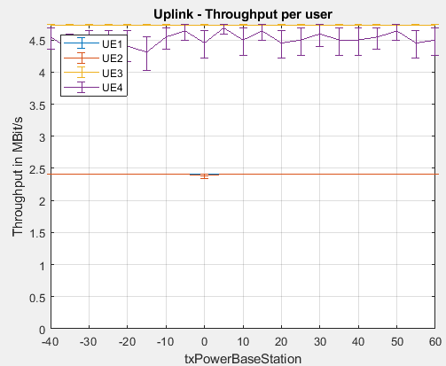
I’ve also tried setting the precoding matrix to 1, but I get the unexpected results where throughput remains constant for OFDMA and NOMA cell centered users, no matter the sweeping the power of the base station (figure for the reference).

uplinkNOMAvsOMA

Thank you for your help in advance.

Best regards,
Džana

Dear Džana,

You cannot set the number of bits manually. The number of transmitted bits depends on the following parameters:

  • Number of subcarriers
  • Frame length
  • Modulation and coding scheme
  • Number of transmitted layers
  • Number of pilots

The layer mapping defines how the codewords are mapped onto the layers, it does not influence the number of transmitted bits.

The path loss is in the LL simulator an input parameter. If you would like to use the path loss models defined by the standard, you have to set the geometric layout to true and choose one of the path loss models (supported options are listed in the generic scenario).

The 3GPP implementation supports up to 64QAM. Higher modulation orders are not included in the 3GPP implementation.

The precoding matrix should be of size nTxAntennas x nLayers. Since you are considering the uplink here and the users are equipped with one antenna, you only have one transmit antenna; therefore, you precoding matrix should be of size 1x1.

You are considering an uplink transmission and sweeping over “txPowerBS”. Since the BS is not transmitting, sweeping over the transmit power of the BS has no impact on your simulations. If you would like to transmit over power, you should sweep over the user transmit power “txPowerUser”.

Best,
Mariam

Dear Mariam,

thank you very much for these detailed explanations.

Best,
Džana

Dear Mariam,

I have 2 more similar questions regarding the similar scenarios like the ones I’ve mentioned above.

  1. I have a question regarding scenario where I am trying to simulate uplink for 4 users and 1 base station on 3.5 GHz and FDD. I am not getting an error, but I keep getting this warning that repeats itself in command window and prevents the execution of simulation. The warning is as it follows: “Warning: Matrix is close to singular or badly scaled. Results may be inaccurate.” I’ve tried simulating the similar scenario for downlink and it works as expected.
    This is my code:
    scStr.topology.nodes = [‘BS1,UE1,UE2,UE3,UE4’];

% Primary (desired) links
scStr.topology.primaryLinks = [‘UE1:BS1,’…
‘UE2:BS1,’…
‘UE3:BS1,’…
‘UE4:BS1,’…
];

% Links for Joint Tranmission and Detection (future work)
scStr.topology.jointTxRxLinks = [‘’];

% Interference Links
scStr.topology.interferenceGeneration = ‘Automatic’;

scStr.topology.attenuation = 300; % in dB, set a very high attenuation level to virtually decouple the two BS
scStr.topology.interferingLinks = [];

%% General Simulation Parameters
% set link types to simulate
scStr.simulation.simulateDownlink = false; % downlink
scStr.simulation.simulateUplink = true; % uplink
scStr.simulation.simulateD2D = false; % device to device links

scStr.simulation.frameStructure = ‘FDD’; % ‘TDD’ or ‘FDD’

% Plot options
scStr.simulation.plotResultsFor = [1];
scStr.simulation.plotOverSNR = false;
scStr.simulation.plotPAPR = false;

scStr.simulation.saveData = false;

% Define a sweep parameter
scStr.simulation.sweepParam = {‘simulation.txPowerUser’}; % Define the parameter to sweep over. This can be almost any simulation parameter.
% Most likely it will be the pathloss to obtain results over SNR.

scStr.simulation.sweepValue = [-40:5:60]; % Define parameter values to sweep over, in dB. A good starting point for the pathloss is 150 to 110
scStr.simulation.applySweepingTo = [1];

% Number of simulation frames
scStr.simulation.nFrames = 200; % Number of frames to simulate per sweep value, adjust to obtain sufficiently small confidence intervals.

%% Physical Transmission Parameters
scStr.simulation.centerFrequency = 3.5e9; % center frequency

scStr.simulation.txPowerBaseStation = [30]; % per BS; base station total transmit power in dBm
scStr.simulation.txPowerUser = [30]; % per UE; user total transmit power in dBm

scStr.simulation.codebook = ‘LTE’; % LTE or 5G
scStr.simulation.nAntennasBaseStation = [2]; % per BS; number of antennas at the base station
scStr.simulation.antennaConfiguration = {[2,1],[2,1]}; % per BS: if the 5G codebook is selected, each vector represents the number of horizontal and vertical antennas[N1,N2]
% Supported configurations (N1,N2):
% 4 Ports: (2,1)
% 8 Ports: (2,2), (4,1)
% 12 Ports: (3,2),(6,1)
% 16 Ports: (4,2), (8,1)
% 24 Ports: (4,3), (6,2),(12,1)
% 32 Ports: (4,4), (8,2), (16,1)
scStr.simulation.nAntennasUser = [1]; % per UE; number of antennas at the user
scStr.simulation.userVelocity = [0]; % per UE; velocity in m/s

% Links to UE1 and UE3 have pathloss of 80, UE2 and UE4 of 90, and UE5 and UE6 of 110 and 115, respectively (cell edge).
scStr.simulation.pathloss = [80,110,80,110]; % per Link, channel pathloss in dB, this is most likely swept over

% Nonlinearity model
scStr.simulation.nonlinearity = false; % Apply Rapp’s PA nonlinear model: Rapp, C. “Effects of HPA-nonlinearity on a 4-DPSK/OFDM-signal for a digital sound broadcasting signal.”
scStr.simulation.amplifierOBO = [1]; % Amplifier output back-off, per Link, in dB
scStr.simulation.smoothnessFactor = [3]; % Smoothness factor for the Rapp model, per Link, >=0

%% Channel Parameters
scStr.channel.spatialChannelModel = false; % for a 3D channel, this parameter has to be set to ture
scStr.channel.dopplerModel = ‘Discrete-Jakes’;
scStr.channel.timeSubsamplingFactor = 10;
scStr.channel.correlatedFrames = false;
scStr.channel.spatialCorrelation = ‘none’;
scStr.channel.nPaths = 50;
scStr.channel.powerDelayProfile = ‘PedestrianA’;
scStr.channel.K = 0;
scStr.channel.delta = 1;

%% Channel Estimation and Equalization Parameters
scStr.simulation.channelEstimationMethod = ‘Approximate-Perfect’;
scStr.simulation.noisePowerEstimation = false;
scStr.simulation.pilotPatternDownlink = ‘Diamond’; % pilot symbol allocation pattern for Downlink links
scStr.simulation.pilotPatternUplink = ‘LTE Uplink’; % pilot symbol allocation pattern for Uplink links
scStr.simulation.pilotSpacingFrequency = 6; % pilot spacing in frequency domain (may be fractions of subcarriers)
scStr.simulation.pilotSpacingTime = 3.5; % pilot spacing in time domain (may be fraction of symbols)
scStr.simulation.pilotSequenceLength = 12; % length of orthogonal pilot symbol sequence
scStr.simulation.receiverTypeMIMO = ‘MMSE’;

%% MIMO Parameters
% Layer mapping
scStr.layerMapping.mode = ‘5G’;
scStr.layerMapping.table.Uplink = {1;2;[1,2]};
scStr.layerMapping.table.Downlink = {1;2;[1,2]};

% MIMO mode
scStr.modulation.transmissionMode = ‘custom’;
scStr.schedule.multiuserMode.Downlink = {‘custom’}; % per BS. Right now ‘MUST’, ‘ZF-MUMIMO’, ‘BD-MUMIMO’ and ‘MRT-MUMIMO’ are supported
scStr.schedule.multiuserMode.Uplink = {‘ZF-MUMIMO’};
scStr.modulation.delayDiversity = 1;

%% Feedback Parameters
scStr.feedback.delay = 0;
scStr.feedback.averager.Type = ‘miesm’;
scStr.modulation.cqiTable = 0;

% for the custom transmission mode the following parameters are used to configure the feedback
scStr.feedback.enable = false; % this parameter is ignored, the feedback is automatically enabled for the CLSM transmission mode
scStr.feedback.pmi = false;
scStr.feedback.ri = false;
scStr.feedback.cqi = true;

scStr.modulation.nStreams = [1]; % per Link; number of active spatial streams
scStr.modulation.mcs = [15]; % parameter is unused
% Per link, precoder selection (used when feedback is disabled)
scStr.modulation.precodingMatrix{1} = sqrt(2); % per Link; employed precoding matrix
% MUST power allocation
scStr.modulation.MUSTIdx = [0]; % per BS; the power allocation index of the 3GPP MUST mode = {0, 1, 2, 3}.

%% Modulation Parameters
% waveform
scStr.modulation.waveform = {‘OFDM’};
scStr.modulation.spreadingTransformDownlink = ‘none’;
scStr.modulation.spreadingTransformUplink = ‘none’;
% parameters for FBMC
scStr.modulation.prototypeFilter = ‘PHYDYAS-OQAM’; % unused for OFDM
% Parameters for UFMC
scStr.modulation.nSubcarriersPerSubband = [12]; % number of subcarriers per subband

% time and bandwidth setup (number of subcarriers, frame duration, CP
% length, sampling rate)
scStr.modulation.numberOfSubcarriers = [144]; % per BS; number of used subcarriers
scStr.modulation.subcarrierSpacing = [15e3]; % per BS; per base station in Hz
scStr.modulation.nSymbolsTotal = [15]; % per BS; total number of time-symbols per frame, the frame duration will be nSymbolsTotal/subcarrierSpacing
scStr.modulation.nGuardSymbols = [1]; % per BS; select how many of the total time-symbols will be used as guard symbols (cyclic prefix in OFDM)
scStr.modulation.samplingRate = ‘Automatic’; % sampling rate has to be the same for all nodes (across all base stations):
% either numeric value for manual setting or ‘Automatic’

%% Channel Coding Parameters
% All links are operating with the same coding parameters, enter it only once.
scStr.coding.code = {‘LDPC’};
scStr.coding.decoding = {‘PWL-Min-Sum’};
scStr.coding.decodingIterations = [16];
scStr.coding.LLRsCalculationMethod = ‘Max-Log’;
scStr.coding.softBufferRatio = [1];

%% Schedule
% static schedule per base station

% BS1 does Orthogonal Multiple Access
scStr.schedule.fixedScheduleDL{1} = []; % schedule for BS1 Downlink
scStr.schedule.fixedScheduleUL{1} = [‘UE1:36,UE2:36,UE3:72,UE4:UE3’]; % No uplink for BS1.

  1. For the second question, I am wondering is there an implementation of scheduling algorithms for resource allocation in the simulator, aside from fixed scheduling (ex. Round Robin or similar)?

Thank you in advance,
Džana

Dear Džana,

According to your scenario, you use a custom multi-user MIMO scheme in the DL. Did you implement a new multi-user MIMO scheme?

Regarding the warning you are receiving:
You have a BS equipped with two antennas serving and four users in your scenario. You need at least four antennas to be able to serve four users. Increase the number of antennas and rerun the simulation; if you still get the same warning, try using MMSE instead of ZF.

On the LLS we only support fixed scheduling.

Best,
Mariam

Dear Mariam,

thank you very much for your help. Using 4x1 MISO solved my problem.

Best,
Džana