At present, there are some problems: (1) After the signal-to-noise ratio is greater than 0, the error rate or frame error rate line drops sharply. When the signal-to-noise ratio is greater than 4dB, the error rate or frame error rate in the simulation image disappears. May I ask where the problem is. I found through my own analysis that when the signal-to-noise ratio is greater than 4dB, the input is completely equal to the output without any errors. But I don’t know why, do you have a suitable explanation here?
(2) In the case you provided, shouldn’t the normal signal-to-noise ratio be 10-20dB? Why is it set to -7 to 1dB here?
(3) The information length K is set to a short length of 48. For LDPC encoding, at least 100000 bits are sent each time. Why is it so short here?
(4) Bit rate issue: The normal bit rate range should be 1/2 or 1/3. Does setting it to 1/8, 1/6 deviate from the actual situation?
At present, I am unable to understand these questions. Can you please answer them
Hello,
The example of “shortBlockChannelCoding” is meant to evalute the performance of the different coding schemes for the scenarios of URLLC and mMTC. In that case, you would usually transmit very short messages (e.g., a command, a sensor reading, etc.), and in the case where high relialbilty is required (e.g., controlling robots, or remote surgery) low coding rate is used. Therefore, in the example given above, the information message is 48 bits, and the coding rate is 1/6 (including CRC). The reason why we selected this scenario is that the default scenario of high rates and long messages (e.g., eMBB) has already been considered heavily in the literature and has already been agreed upon by 3GPP (LDPC for data, and polar for control), so we wanted to consider a different case.
Now to your questions:
-
This is because the BER becomes very low; it drops quickly to very low levels. In order to capture it, you need to increase the number of simulated frames. For eaxmple, to see stable results for an FER of 10^-3, you should simulate at least 10^4 frames or so, such that you capture the low-probablilty event of a frame failure.
-
No, the channel is AWGN and we are operating with a low coding rate and low modulation order. For such a setup, the schemes can already give very low BER at low SNRs.
-
As I explained above, in this example we are using short block lengths. I am not sure where you are seeing the length of 100000 bits. I just checked it and the length of “CodedBits” is exactly 384, which is 48x8.
-
As before, it is just the example scenario we used.
You can always change the lengths, coding rates, modulation order, channel models, etc, as you wish. The example was just meant to show you how you can do that, while considering the scenario of URLLC and mMTC, which at that time was under heavy research by 3GPP for Rel-16 and afterwards.
Best regards,
Bashar
I am very pleased to receive your letter. It is your explanation that has solved my current confusion.
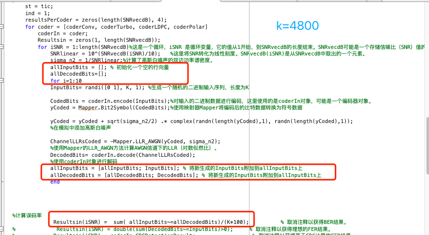
Now I have another question to ask you. The signal-to-noise ratio disappears after 4dB. Can we improve it by increasing the length of input information. But based on my understanding of this code, when K=480000, there is an error in the code. It seems that this code does not support long information lengths. The above is my modified code. By looping in the value of K=4800 100 times, the program runs normally first, but the simulation results remain unchanged from before. Excuse me, is there a problem with my code
Hello, I have another question. How much can the K value change? When selecting the K value, I made an error when it was greater than 10000. If I want to increase the K value, for example, K=48000, how should I modify the code so that it does not make an error?
Hello,
The implementation of the coding schemes follows the 3GPP standardization (except for the polar code). In LTE, the convolutional and turbo codes information length is limited to Z = 6144; we also use this limit for the polar code. For the LDPC codes, which are based on 5G-NR, it is either 8448 or 3840 depending on whether base-graph 1 or 2 is selected. The selection of the base-graph depends on the input length and the coding rate.
If your K is longer than these limits, then code-block segementation is performed where the long information message is broken into small blocks, each not exceeding the limits above. In the simulator, this operation is performed in the function “update()” of the file “ChannelCoding.m”. Therefore, if you set K very long, it will be broken into small blocks, each encoded separately.
As for the error, since the procedure follows 3GPP standardization, when you supply a long information message, you also need to properly set up the other paramters. For example, for LDPC, long lengths segementation only works in combination with a CRC of length 24, and with code-rates exceeding 2/3.
Please refer to the simulator manual pdf for more information about the implementation, and for the 3GPP documentation for more information about the segmentation process.
LTE: https://www.etsi.org/deliver/etsi_ts/136200_136299/136212/15.02.01_60/ts_136212v150201p.pdf
5G-NR: https://www.etsi.org/deliver/etsi_ts/138200_138299/138212/16.02.00_60/ts_138212v160200p.pdf 1
Best regards,
Bashar
Thank you very much for your reply. I have gained a deeper understanding of this code.
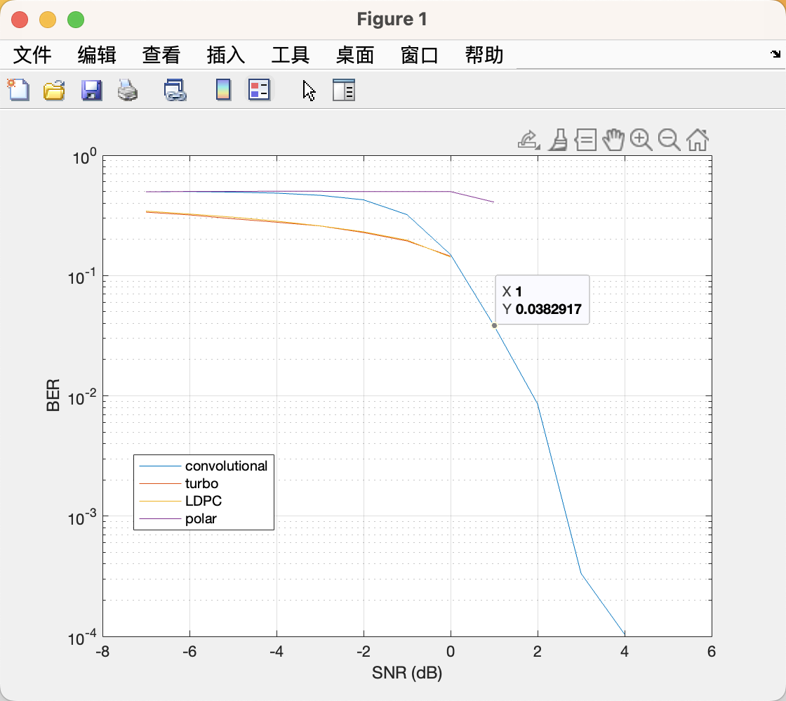
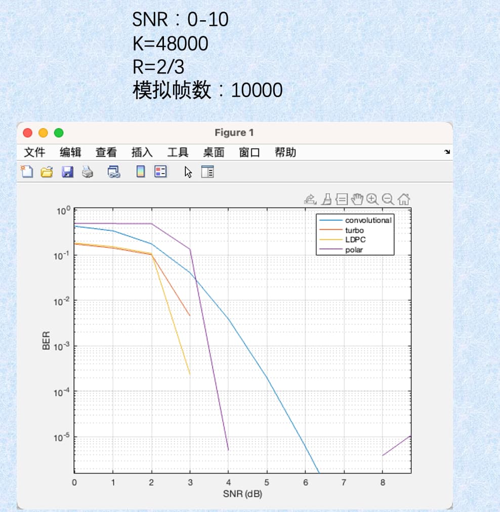
Now there is a new problem that arises when I set the parameter SNR: 0:1:10; K=48000; R=2/3; When numR=10000, when the signal-to-noise ratio is greater than 4dB, only the convolutional code has BER, and other codes still break after 4dB, as shown in this simulation diagram. (1)Is it because there aren’t enough simulations?
(2)Another question is whether the length of information K has an impact on BER?
(3)When my message length K=480000, what is the bit rate set to avoid errors.
Besides, I have another question. I want to compare these four encodings under normal circumstances, such as a signal-to-noise ratio of 10-20dB, information length of around 100000, and a bit rate of 1/2 or 1/3. In this case, compare the BER of the four encodings.
(1) Can I directly modify the encoding length, bit rate, and signal-to-noise ratio to see BER in the shortBlockChannelCoding. m scene?
(2)If it’s not possible, how should I modify this scene?
Hello,
(1) Yes, the BER is very low at these levels that you need to simulate more frames to capture an event of error.
(2) Yes. If the code is capacity-approaching, which is the case for the turbo, LDPC, and polar codes, then the longer the codeword is, the sharper the drop in the BER curve will be as the SNR increases.
(3) It seems that this length is not compatible with the 3GPP codeblock segementation. Try another length.
(4) To evaluate the performance in a realistic range, you need to have a realistic setup. Instead of the simple AWGN channel, i.e, y = x + n, you can use a fading channel, i.e, y = h*x + n, where h is the fading coefficient, e.g., Rayleigh. At the receiver side, you need to first equalize for the channel through “y ./ h”. Then, in the Mapper.LLR_AWGN() function, instead of just passing “sigma_n2”, you pass “sigma_n2 ./ abs(h).^2”. If you have selective fading, then h will be a vector of course.
You can of course also increase the SNR range for detectability by increasing the modulation order.
Best,
Bashar
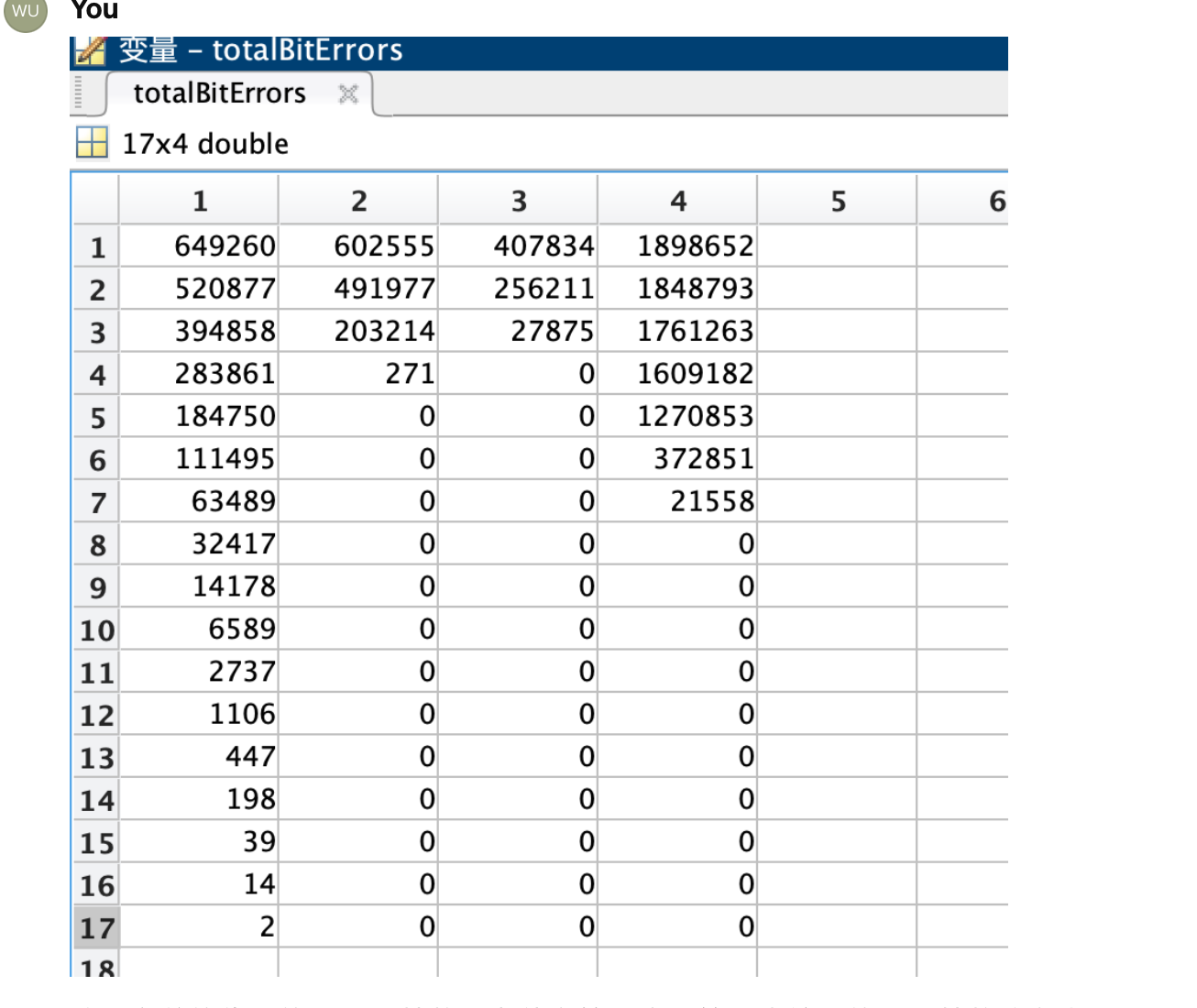
This is the code modified based on your suggestion: analog frame rate 1000, information length K=4800. I wrote a code that loops 10 times when inputting, which is equivalent to inputting a signal with an information length of 48000; Modulation order: 16; The code rate is R=1/2; Also written in the code of Ruili’s decline. The above figure shows the bit error numbers of convolutional codes, Turbo codes, LDPC codes, and Polar codes.
My question is: Why is the bit error rate 0 after a signal-to-noise ratio of 4dB in the last three encodings?
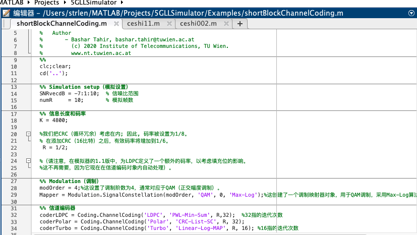
%% Short block length comparison between Convolutional, Turbo, LDPC, and Polar Codes (journal example).
% Author
% - Bashar Tahir, bashar.tahir@tuwien.ac.at
% (c) 2020 Institute of Telecommunications, TU Wien.
% www.nt.tuwien.ac.at
clc; clear;
cd(‘…’);
%% Simulation setup(模拟设置)
SNRvecdB = 7:0.5:15; % 信噪比范围
numR = 1000; % 模拟帧数
%% 信息长度和码率
K = 4800;
R = 1/2;
%% Modulation(调制)
modOrder = 16;
Mapper = Modulation.SignalConstellation(modOrder, ‘QAM’, 0, ‘Max-Log’);
%% 信道编码器
coderLDPC = Coding.ChannelCoding(‘LDPC’, ‘PWL-Min-Sum’, R, 32);
coderPolar = Coding.ChannelCoding(‘Polar’, ‘CRC-List-SC’, R, 32);
coderTurbo = Coding.ChannelCoding(‘Turbo’, ‘Linear-Log-MAP’, R, 16);
coderConv = Coding.ChannelCoding(‘TB-Convolutional’, ‘Max-Log-MAP’, R);
%% 初始化
coderLDPC.CustomCRC = 1;
coderPolar.CustomCRC = 1;
coderTurbo.CustomCRC = 1;
coderConv.CustomCRC = 1;
coderLDPC.CRCPoly = ‘24A’;
coderLDPC.CRCLength = 24;
coderPolar.CRCPoly = ‘24A’;
coderPolar.CRCLength = 24;
coderTurbo.CRCPoly = ‘24A’;
coderTurbo.CRCLength = 24;
coderConv.CRCPoly = ‘24A’;
coderConv.CRCLength = 24;
coderLDPC.update(‘Input’, K, 1, R, log2(modOrder), 1);
coderPolar.update(‘Input’, K, 1, R, log2(modOrder), 1);
coderTurbo.update(‘Input’, K, 1, R, log2(modOrder), 1);
coderConv.update(‘Input’, K, 1, R, log2(modOrder), 1);
%% 初始化总误码数
totalBitErrors = zeros(length(SNRvecdB), 4);
%% Simulation loop(模拟循环)
fprintf([‘------- Started -------’, ‘\n’]);
d = tic;
for m = 1:numR
st = tic;
ind = 1;
for coder = [coderConv, coderTurbo, coderLDPC, coderPolar]
coderIn = coder;
for iSNR = 1:length(SNRvecdB)
SNRlinear = 10^(SNRvecdB(iSNR)/10);
sigma_n2 = 1/SNRlinear;
        allInputBits = []; % 初始化一个空的行向量
        allDecodedBits = [];

        for i = 1:10
            InputBits = randi([0 1], K, 1);
            CodedBits = coderIn.encode(InputBits);
            yCoded = Mapper.Bit2Symbol(CodedBits);

            % 生成衰落系数 h
            h = (randn(length(yCoded),1) + 1i*randn(length(yCoded),1))/sqrt(2); % 对于瑞利衰落

            % 应用衰落信道
            yCoded = h .* yCoded + sqrt(sigma_n2/2) .* complex(randn(length(yCoded),1), randn(length(yCoded),1));

            % 接收端均衡
            y_eq = yCoded ./ h;

            % 修改 LLR 计算
            ChannelLLRsCoded = -Mapper.LLR_AWGN(y_eq, sigma_n2 ./ abs(h).^2);

            DecodedBits = coderIn.decode(ChannelLLRsCoded);
            allInputBits = [allInputBits; InputBits]; % 将新生成的InputBits附加到allInputBits上
            allDecodedBits = [allDecodedBits; DecodedBits]; % 将新生成的DecodedBits附加到allDecodedBits上
        end

        % 更新总误码数
        totalBitErrors(iSNR, ind) = totalBitErrors(iSNR, ind) + sum(allInputBits ~= allDecodedBits);
    end
    ind = ind + 1;
end
en = toc(st);
fprintf('Repetition %i/%i.\n', m, numR);
end
fprintf([‘-------- Done --------’, ‘\n’]);
toc(d)
%% 计算平均误码率
averageBER = totalBitErrors / (K * 10* numR);
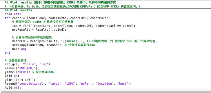
%% Plot results
hold off;
coderNames = {‘Convolutional’, ‘Turbo’, ‘LDPC’, ‘Polar’};
for i = 1:length(coderNames)
semilogy(SNRvecdB, averageBER(:, i));
hold on;
end
% 设置图表属性
set(gca, ‘YScale’, ‘log’);
xlabel(‘SNR (dB)’);
ylabel(‘BER’); % 显示为误码率
grid on;
ylim([1e-4 1e0]);
legend(coderNames, ‘location’, ‘best’);
hold off;
%%This is the code I have modified. Please check it.
It is zeros because no bit errors occured during the simulation repetitions. The BER is already very low at such an SNR for the given setup. To capture an error at such low BERs, you need to simulate many more frames, before you see a codeword in error. To see smoother changes in the curve, you can try to decrease the SNR step. So instead of a step of 0.5, you can try something like 0.1. With such a small step, you might be able to better capture the drop in the curve.
Regarding the simulation of 10x4800 bits codewords, you need to be careful here. Simulating 10 codewords of information length 4800 is not the same as simulating a long codeword of length 48000. The longer the codeword is, the better the decoding performance will be; the long codeword will have a steeper BER slope.